Chapter 3 : Setting up a lumped parameter model
5.1. Setting up analysis reflexes : Storage and dissipative effect
1) Depending on the phenomenon to be modelled, tick in the table according to the physical domain and the type of effect to be taken into account :
1) a and f
2) b/c and h
3) b/c and g
4) a and h
5) e and h
6) a and g
7) d and f
8) e and f
9) e and h
10) c and g
11) b/c and f
12) d and h
13) d and f
2) For the technical devices represented below, indicate the dominant effect for each part (a) to (e) :
a) Spring
b) Inertia (mass in translation)
c) Capacitance
d) Rotary spring and viscous damping
e) Inertia in rotation
5.1. Setting up analytical reflexes : Transforming effects
1) Demonstrate that the transformation ratios $k_c$ and $k_e$ are identical
Ideal direct current motor :
\begin{align}
P_{Rotation} &= P_{Electrical} \
C.ω &= E.I \
k_C.I.ω &= k_E.ω.I \
k_C &= k_E
\end{align}
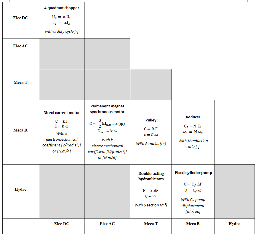
2) Complete the table below by indicating the components and corresponding equations of the following two devices
5.2. Geometry / network link : analysis of a power steering system
1) Surround in the table according to the Modelica component
1) Direct current motor : c
2) Wheel and worm screw : e
3) Non-contact torque sensor : f
4) Clutch : d
5) Rack and pinions : g et h
2) Propose a Modelica diagram modelling the DC motor and taking into account the transformer, dissipative and energy storage effects at both mechanical and electrical levels.
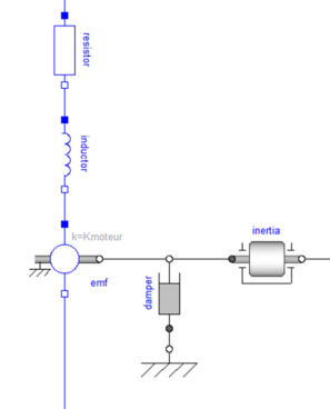
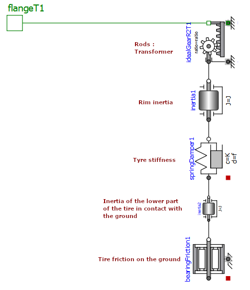
3) Indicate on the diagram the effects represented by each of the Modelica components
5.3. Systematic effects analysis: analysis of a common rail direct injection system
1) Mechanics : source of rotational speed
2) Mechanical/Hydraulics : Transformer
3) Hydraulics : Capacity
4) Hydraulics : Flow source
5) Hydraulics : Variable hydraulic resistance
6) Hydraulics : Pressure source